Protek 3000 SERIES
STORAGE OSCILLOSCOPES
DIGITAL STORAGE OSCILLOSCOPE Protek 2 000 SERIES
Features
200 / 100 / 60 MHz Bandwidth with 2 Channels
500 Msa /s and 1Gsa / s Real – Time Sampling Rate,
50 Gsa /s Equivalent - Time Sampling Rate
Large 5.7 inch TFT Color Display
Three Math Functions Including “+”, “-“ and “FFT”
Multi-Languages Support
USB (Host & Device), RS 232 & RJ45 Interface
Battery Power Operation (Optional)
MODEL
Protek 3006
Protek 3010
Protek 3110
Protek 3020
Protek 3120
Channels
2
2
2
2
2
Bandwidth
60MHz
100MHz
100MHz
200MHz
200MHz
Rise Time
5.8ns Approx
3.5ns Approx
3.5ns Approx
1.8ns Approx
1.8ns Approx
Input Impedance
Resistance : 1M ± 2% , Capacitance : (20 ± 5) pf
Polarity
Normal & Invert
Maximum Input
400V (DC + AC Peak)
Waveform Signal Process
Ch1 ± CH2, CH1 x CH2, CH1/CH2, FFT
Bandwidth Limit
20MHz / -3dB
40MHz / -3dB
Source
CH1, CH2, EXT, City Electricity
Mode
Edge, Pulse, Video, Slope Trigger
Sensitivity
Max, 1div (Frequency upper Limit to 40MHz), Max, 2 div, TV-V, TV-H Video Trigger
Ext. Trigger Input Impedance
Resistance : 1Mohm ±2%; Capacitance: (20 ± 5) pF
Ext. Trigger Sensitivity
Max. 100m v p-p (Frequency upper limit to 40 MHz)
Max. input Voltage
400V (DC+AC Peak)
Low Frequency Inhibition
Frequency < 100KHz will be inhibited
High Frequency Inhibition
Frequency > 100KHz will be inhibited
Sampling
Real-time Max, Sampling Rate : 0 Series is 500MSa / s, 1 Series is 1GSa / s
Range (1.2.5 increments)
50s/div ~ 10ns/div
50s/div ~ 5ns / div
50s/div ~ 1ns / div
Mode
Main Sweep, Main Sweep + Delay Expansion Sweep, X-Y
X-Axis Input
Channel 1
Y-Axis Input
Channel 2
Phase Shift
Max 3 degree @ 5MHz
Voltage Measurement
Vpp, Vamp, Vrms, Vhi, Vio, Vmax, Vmin, Pre-shoot, Overshoot
Time Measurement
Frequency, Rise time, Fall time, Positive Width, Negative Width, Duty Cycle
Delay Measurement
Delay 1->2 , Delay 1- > 2
Cursor Measurement
Voltage difference between Cursors Δ V, Time difference between Cursors Δ T
TFT LCD Type
5.7 Inch
Display Resolution
240 (Vertical) x 320 (Horizontal) Dots
RS 232 Interface
DB-9 Pin RS 232 Interface
USB
USB Host / Device 2.0 Full Speed Supported
Line Voltage Range
AC 100V – 240V ± 10%, 45Hz – 440Hz, Auto Selection
Battery Power (Option)
Li-ion Battery Pack
Dimension
300 x 150 x 130 (mm)
Weight
2.5 kgs.
PROTEK HANDHELD SCOPE METER SERIES
Features:
600/500/200 MHz Bandwidth with 2 Channels
2Gsa/s, 1Gsa/s, 500Msa/s,250 Msa/s and 150Msa/s Real – Time Sampling Rate,
50Gsa/s Equivalent-Time Sampling Rate
6,600-Count DMM resolution with AC/DC at 600V, 10A
Large 5.7 inch TFT Color Display
Multi-Languages Support
USB Host / Device 2.0 full-speed interface connectivity
Battery Power Operation (Installed)
SPECIFICATIONS
Protek 1006
Protek 1020
Protek 1050
Protek 1160
Protek 1260
Vertical
Channels
2
2
2
2
2
Bandwidth
60MHz
200MHz
500MHz
600MHz
600MHz
Rise Time
5.8 ns
1.7 ns
0.58ns
Input Impedance
Resistance : 1 MΩ ; Capacitance : 15 pF
Input Sensitivity
10 mV /div to 5V /div
Input Coupling
AC, DC with Ground Level Indicator
Vertical Resolution
8 bits
Memory Depth
32K at Single Channel, 16K at Dual Channel
Maximum Input
300V (DC + AC Peak)
Horizontal
Sampling
150MSa/s
250MSa/s
500mSa/s
1GSa/s
2GSa/s
Equivalent Max. Sampling Rate is 50GSa /S for all items
Time Base Range
5ns/div ~ 1000s/div
2ns/div ~1000s/div
1ns/div ~ 1000s/div
Time Base Precision
± 50ppm
Trigger
Source
CH1, CH2
Mode
Edge, Pulse Width, Alternative
Edge, Video, Pulse Width, Alternative
X-Y mode
X-Axis Input
Channel 1
Y-Axis Input
Channel 2
Phrase Shift
Max. 3 degree
Cursors and Measurement
Voltage measurement
Vpp, Vamp, Vmax, Vmin, Vtop, Vmid, Vbase, Vavg, Vrms,Vcrms,Preshoot, Overshoot
Time Measurement
Frequency, Rise Time, Fall Time, Positive Width, Negative Width, Duty Cycle
Delay Measurement
Delay 1 -> 2 , Delay 1 -> 2
Cursors Measurement
Manual, Track, Auto Measure Modes
Waveform Signal Process
CH1 ± CH2, CH1 x CH2, CH1 / CH2, FFT, Invert
Storage
15 Waveforms and Setups
Meter mode
Maximum Resolution
6,600 Counts
DMM Testing Modes
Voltage, Current, Resistance, Capacitance, Diode & Continuity
Maximum Input Voltage
AC : 600V, DC : 600V
Maximum Input Current
AC : 10A, DC : 10A
Input Impedance
10 MΩ
Display
TFT LCD Type
5.7 Inch with LED Backlight Display
Display Resolution
240 (Vertical) x 320 (Horizontal ) Dots
Interface
USB
USB Host/Device 2.0 Full Speed Supported
Optional
Rs 232, LAN
Power source
Line Voltage Range
AC 100V ~240V, 50Hz ~ 60 Hz, DC Input: 8.5 VDC, 1500mA
Battery Power (Installed)
6 Hours
Physical Parameters
Dimension
245 x 163 x 52 (mm)
Weight
1.2 Kgs.
Others
GND Reference
Oscilloscope and Multimeter Independence
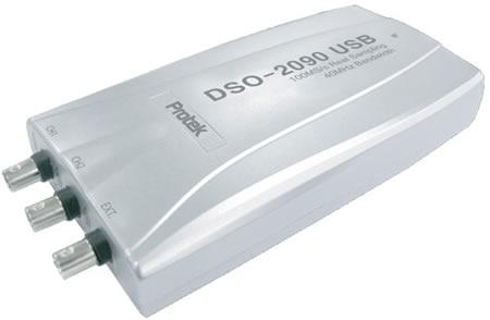
VIRTUAL STORAGE OSCILLOSCOPE DSO SERIES (PC Based DSO)
MODEL
DSO-2090
DSO-2150
DSO-2250
DS0-2500
DS0-5200
DS0-5200A
Max Sample Rate
Real-time
100MS/s
150MS/s
250MS/s
500MS/s
100MS/s using 1 Channel
100MS/s
Equivalent Sampling
5GS/s
25GS/s
Bandwidth
40MHz
60MHz (+3dB)
100MHz
200MHz (-3dB)
200MHz (-3dB)
200MHz (-3dB)
Single Shot bandwidth
40MHz
60MHz
100MHz
200MHz
50MHz
100MHz
Butter Size
32K Samples
10K to 512 K Samples
Channels
2 Channel
10mV to 5V/div @ x1 probe
10mV to 10V/div @ x1 probe
100mV to 50V/div @ x10 probe
100mV to 100V/div @ x 10probe
Voltage Range
1V to 500V/div @ x 100 probe
1V to 1000V @ x 100 probe
10V to 5000V/div @ x 1000 probe
10V to 10000/div @ x 1000 probe
Accuracy
± 3 %
Time base Range
4ns / div to 1h / div (1 – 2 – 4 sequences)
2ns / div to 1h / div (1 – 2 – 4 sequences)
Offset Level
± 4 division
Coupling
AC / DC / GND
Impedance
1m Ohm
Input Protection
35V pk ( DC + peak AC, without external attenuation )
Roll mode
1 s / div to 1h / div
Range
10 divisions
Pre/post Trigger
0 % to 100 %
Trigger Type
Edge Trigger: Rising Edge : falling edge
Trigger Mode
Auto Normal & Single
Autoset
Yes
Settability
0.03 div increments
Trigger Level
± 4 division
Measurements
Vp-p, Vmax, Vmin, Vmean, Vrms, Vhigh, Vlow, positive overshoot, negative overshoot, cycle mean, cycle rms, period, frequency, positive pulse width, negative pulse width, rise time (10% to 90%), positivity duty Cycle. negative duty cycle
Cursor
Time / frequency difference, Voltage difference
Math
Addition, Subtraction, Multiplication and Division
FFT
Rectangular, Hanning , Hamming, Blackman Window
Interface
Universal Serial Bus (USB)
Power
No External Power sources required
Bus Power From USB 1.7 W
calibration single output
2V, 1KHz, Square Wave
Trace display
Point / Line
Vertical Position Variable
Yes
Grid
On/Off
Image Save : BMG, JPG
Data Save: DSO
File Management
OLE (Object Linking and Embedding ) automation : Data generation for Microsoft Excel
Setting Save / load
Print
Print in color / Mono
PC Based Arbitrary Waveform Generator/ Counter (DDS-3005)
Frequency Range
0.1 Hz (DC) to 5 MHz
Frequency Resolution
0.01 Hz
DAC Clock
0 to 50 MHz continuously adjustable in 0.2 Hz step
Channels
1 CH waveform output
Waveform Depth
256KSa
Vertical Resolution
14 Bits
Frequency Stability
< 30 ppm
Frequency Amplitude
0 to ± 10V
Output Impedance
100Ω
Output Current
50mA Vpeak = 100 mA
Low Pass Filter
5 MHz, 1 MHz, 100 KHz, 10 KHz, 1 KHz, Programmable
DC Accuracy
± 0.1% (FS)
AC Accuracy
± 0.2%
Harmonic Distortion
-65 dBc (1KHz), -53 dBc (100KHz)
Range
DC to 25 MHz
Input Amplitude
200 mVpp to ±25Vpp
Coupling Mode
AC, DC Programmable
Accuracy
1 Hz
Input Impedance
> 500K
Range
25 MHz to 2.7 GHz
Input Power
20 dbm
Coupling Mode
AC
Accuracy
256Hz
Input Impedance
50Ω
Digits
8 Bits + Sync. 1 Bit + Ext. Trigger 1 Bit
Level
3 / 5V TTL / CMOS
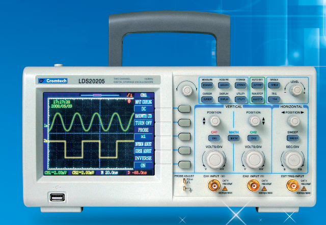
LD20000 Series Digital Storage Oscilloscope
Vertical two channels, bandwidth of each channel is 200MHz,100MHz, 60MHz, 40 MHz, 25 MHz;
5 series real-time max.sampling rate is 500MSa/s,
10 series is 1GSa/s equivalent max.sampling rate is 50Gsa/s
High LCD, adjustable intensity;
Support communication interface. RS232, USB(main sub), RJ45 LAN;
Delay sweep,shorten time;
Measure Multi-waveform parameters automaticall, record and recall waveform;
SFFT, differential coefficient, integral and FFT analysis;
Multi-language menus display,help to display information;
Input attenuation 2mV/div~50V/div,easy to measure big signal;
Display date and time;
Auto-track:Sweep auto-track,vertical auto-track,completely auto-track;
Edge,video,pulse width,slope,alt,etc;
Pass/Fail measure;
Kinds of correction signals output frequency(1K,10K,100K).
Specification LDS22005 LDS21005 LDS20605 LDS20405 LDS20205
Vertical System
Channel
CH1,CH2,analog-digital switch,8 bit resolution
Vertical deflexion
2mV/div~50V/div,1-2-5,14steps
Anglog bandwidth
200MHz
100MHz
60MHz
40MHz
25MHz
Single bandwidth
DC~200MHz
DC~100MHz
DC~60MHz
DC~40MHz
DC~25MHz
Expansion bandwidth(2mV/div)
DC~40MHz(200MHz product) -3dB DC~20MHz(<100MHz product) -3dB
Analog frequency bandwidth limit,classic
40MHz(200MHz product) -3dB
Rising time
≤1.8ns
≤3.5ns
≤5.8ns
≤8.7ns
≤14ns
LF limit (AC coupling)
≤10Hz(on BNC)
Probe attenuation coefficient
1×,10×,100×
Dynamic range
≥12div(screen central baseline±6div)
Input impedance
Resistance(1±2%)MΩ capacitance(20±5)pF
Max.input voltage
400V(DC+ACPEAK) frequency≤400Hz(when impedance is 1MΩ)
Allowed deflexion parameters error
≤±(3%+one pixel)(>5mV/div) ≤±(4%+one pixel)(>2Mv/div)
Common-mode rejection ratio
≥20dB at 50MHz
Open circuit noise
≤0.4div at 5mV/div step
Float
Short-term floar; ≤0.5div long-term; ≤1div
Working mode
CH1,CH2,CH1±CH2,CH1×CH2,CH1/CH2,FFT
Probe
Probe
1×location 10×lovation
Bandwidth
DC~6MHz DC~DC~full bandwidth
Attenuation
1:1 10:1
Compensation
10pF-35pF oscilloscope 1MΩ input impedance
Input impedance
(1±2%) MΩ (10±2%) MΩ
Input capacitance
About 100pF about15pF
Horizontal System
Sampling
Real-time Max.sampling rate 05 series is 500MSa/s,10 series is 1GSa/s Equivalent Max.sampling rate is 50Gsa/s
Waveform interpolation
Sin(x)/x
Record length
4kB/CH can expand to 256MB or 512MB
Horizontal working mode
Main sweep,main sweep+delay expansion sweep,X-Y
Sweep time base
1-2-5 50s/div~Ins/div(200MHz product):50s/div~5ns/div(100MHz product)
Sampling rate and delay time precision
±100ppm
X-Y characterstic
X(CH1)frequency bandwith DC~vertical full bandwidt -3dB phase error: ≤3° at 5MHz
Trigger
Trigger soure
CH1,CH2,EXT,city electtricity
Ext.trigger input impedance
Resistance(1±2%) MΩ capantance(20±5)pF
Max.input voltage
400V(DC+Acpeak) ≤1kHz
Trigger sensitivity
Internal: ≥1div(frequency upper limit to 40MHz), ≥2div(>40MHz), ≥2div,TV-V,TV-H video trigger
Auto-trigger range
100Hz~100MHz square-wave signal
Trigger level range
Internal trigger: ±4div external trigger: ±1.6V
Low frequency inhibition
Frequency about<100KHz will be inhibitted
High frequency inhibiton
Frequency about>100KHz will be inhibitted
Trigger mode
Edging trigger,pulse trigger,video trigger,slope trigger
Measure
Cursor measure
Measure voltage error between cursors△V,
Auto-measure
Voltage parameters: p-p,amplitude,Max,Min,top,bottom,average,root-mean-square value,overshot,pre-overshot.
Display Screen
5.7inch,color
Pixel of waveform display region
Vertical:200dot(full),25dot/div
Display mode
Dot,vector
Display mode
Normal
Calibrate
Amplitude
0.5Vp-p≤±1%
Frequency
1KHz,10KHz,100KHz square-wave
Output
Output interface
USB,RS232,RJ45 LAN(optional)
Storage
Waveform storage
10 teams
Setup storage
10 teams
Mechanical
Power voltage
AC100V~240V±10% 45Hz~440Hz
Power
@25W
Dimension and weight
300mm×150mm×130mm 2.5kg